MainBox
One of the primary functions of the MainBox is to mount the Panasonic PC onto the body of the construction machine.
This can be achieved in two ways:
- Using three integrated magnets (MainBox[14]), allows flexible mounting at various locations on the machine body.
- Using four VESA-standard mounting nuts located on the back of the MainBox (MainBox[15]).
Power Management
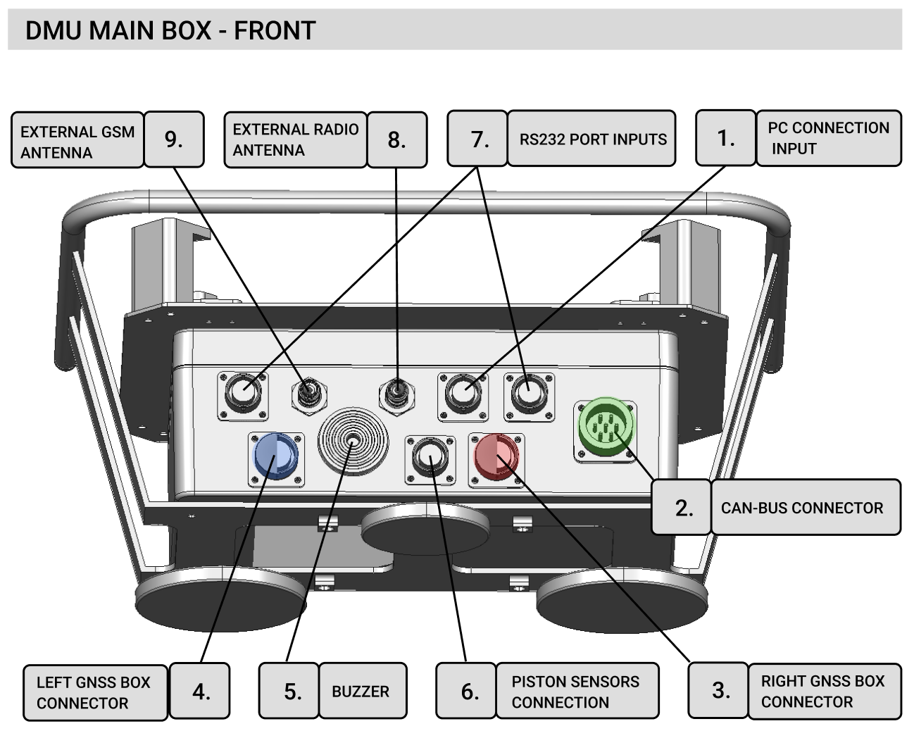
The MainBox features a built-in power management system, including battery management. When the main power supply (from the construction machine) is connected via the CAN connector (MainBox[2]), it powers the following components:
- Panasonic PC
- Both DMU GNSSBoxes, through connections between MainBox[4|6] and GNSSBox[1] The integrated battery enables autonomous operation, which is useful during system setup, configuration, or maintenance work in the field when the main power source is unavailable.
Device communication and RTK Correction Distribution
When the Panasonic PC is connected to the MainBox via MainBox[1] → PanasonicPC[2], the computer will detect the connected devices as /dev/tty* or /dev/usb* interfaces. Another core functionality of the MainBox is to distribute RTK corrections to the connected GNSSBoxes.
This can be done in three ways depending on the configuration:
- LTE RTK Configuration The MainBox is provided with the RTK server address, port, and user login credentials. It connects to the RTK server using its built-in LTE modem and forwards the received RTK corrections to the GNSSBoxes.
- Radio RTK Configuration The MainBox receives RTK corrections through its internal radio receiver and, similar to the previous setup, forwards them to the GNSSBoxes.
- External RTK Source Configuration In this setup, the MainBox does not manage RTK correction reception (LTE and radio are disabled). RTK corrections are instead provided directly from the Panasonic PC to the serial ports of the GNSSBoxes using the DMU application or another external software.
The RTK correction mode can be configured either via the serial debug port on the MainBox, or directly within the DMU application. For radio-based corrections, a radio antenna must be connected to MainBox[8]. For LTE-based corrections, the MainBox is equipped with a permanently connected main LTE antenna (MainBox[12]). In case of weak GSM coverage, an external antenna (e.g., a whip antenna) can be connected to MainBox[9] and mounted on the roof of the machine for better reception. To enable internet access via LTE, insert an unlocked SIM card (with PIN lock disabled) into MainBox[13]. Be sure to secure the SIM cover tightly to prevent water ingress. The LTE connection status is indicated by the status LED on MainBox[11], providing the user with visual feedback on connectivity.
LED status indicator:
| LTE status | Color | Light type |
|---|---|---|
| LTE not connected | RED | blink 1Hz |
| LTE connected | RED | lights |
| LTE connected + RTK correction stream OK | GREEN | lights |
External Positioning Devices
The user can also use external devices to determine the machine’s position – for example, third-party GNSS receivers or total station controllers equipped with an RS232 communication port, or with an appropriate adapter if necessary. These devices can be connected via MainBox[7] connectors. The device is also equipped with a CAN interface for direct communication with the construction machine (in the current version, communication is only supported with machines manufactured by Wirtgen). Through the MainBox[2] connector, the computer sends commands directly to the construction machine. The cable required to connect the MainBox to the machine is not included with the device. In the event of a communication failure with the construction machine, the user can be notified by an audible signal using the buzzer on MainBox[5].
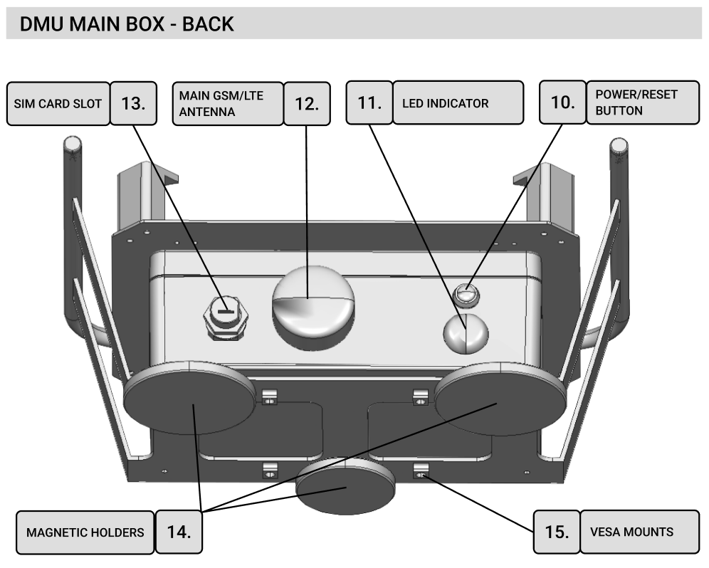
To reset the MainBox device, use the button labeled MainBox[10]; it must be held for 5 seconds. A reset is necessary when changing the device configuration or uploading new firmware.