Calibration offset measuring
The position of the road milling machine is determined continuously by two GNSS receivers mounted at the rear of the machine (on the engine cover) using magnetic mounts. This position is not precisely specified as each model of road milling machine has different dimensions and therefore an initial calibration measurement must be made for each individual machine.
Using the calibration values, it is possible to calculate the position of the milling drum axis and therefore the position in which to set the milling depths and inclination (hereinafter referred to as reference point of milling parameters). The connection of the left and right GNSS receivers defines the X axis of the local coordinate system and the Y axis is a complement to the mathematical cartesian system.
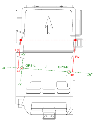
With the total station it is necessary to determine the parameters - Ly, Lx, Ly, Ry, Rx and Rz (see figure). The position of the magnetic holders is chosen approximately parallel to the axis of the milling drum and at least 0.5 m from the milling machine cabine (to not shield GNSS signals).
Explanation of calibration values:
- Lx – X offset of the left side of the milling drum from the left GNSS receiver.
- Rx – X offset of the right side of the milling drum from the right GNSS receiver.
- Ly – Y offset of the left side of the milling drum from the left GNSS receiver.
- Ry – Y offset of the right side of the milling drum from the right GNSS receiver.
- Lz – Z (height) offset of left GNSS receiver from milling drum axis.
- Rz – Z (height) offset of right GNSS receiver from milling drum axis.
X (Lx and Rx) offsets are determined relative to the position of the GNSS receivers i.e., without including the mutual distance d.
How to measure calibration values?
Measuring workflow:
- Place the magnetic holders on the roof of the milling machine - approximately parallel to the milling drum axis and at least 0.5 meters from the machine cabine,
- Mark this location with, for example, an alcohol pencil or sticker - important for later placement in the same position,
- Measure the distance between the centers of the magnetic bracket screw (distance
d), - Align the milling machine to a horizontal position i.e., the cross-inclination sensor should read 0%,
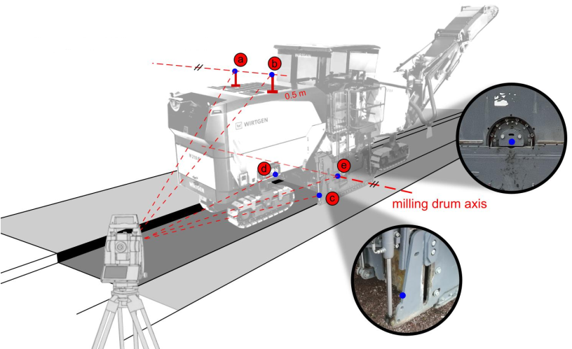
- Place the total station behind the machine so that both magnetic holders, the right side with the axis of the milling drum and the left side plate on the other side of the machine are visible,
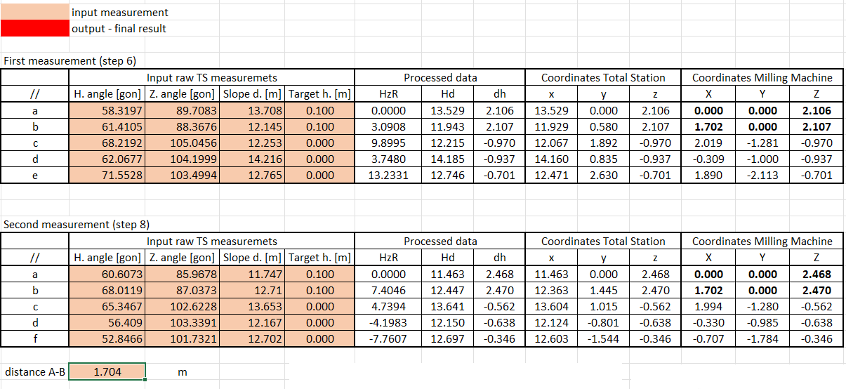
- Measure these points:
- (a) Left magnetic holder screw,
- (b) Right screw of the magnetic holder,
- (c) Centre of the side plate - right side,
- (d) Centre of the side plate - left side,
- (e) Axis of the milling drum – right side.
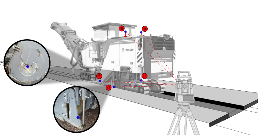
- Move the total station to the second position so that both magnetic holders, the left side with the cylinder fixing screw and at the same time the right-side plate on the other side of the machine are visible again,
- Measure these points:
- (a) Left magnetic holder screw,
- (b) Right screw of the magnetic holder,
- (c) Centre of the side plate - right side,
- (d) Centre of the side plate - left side,
- (f) Axis of the milling drum – left side.
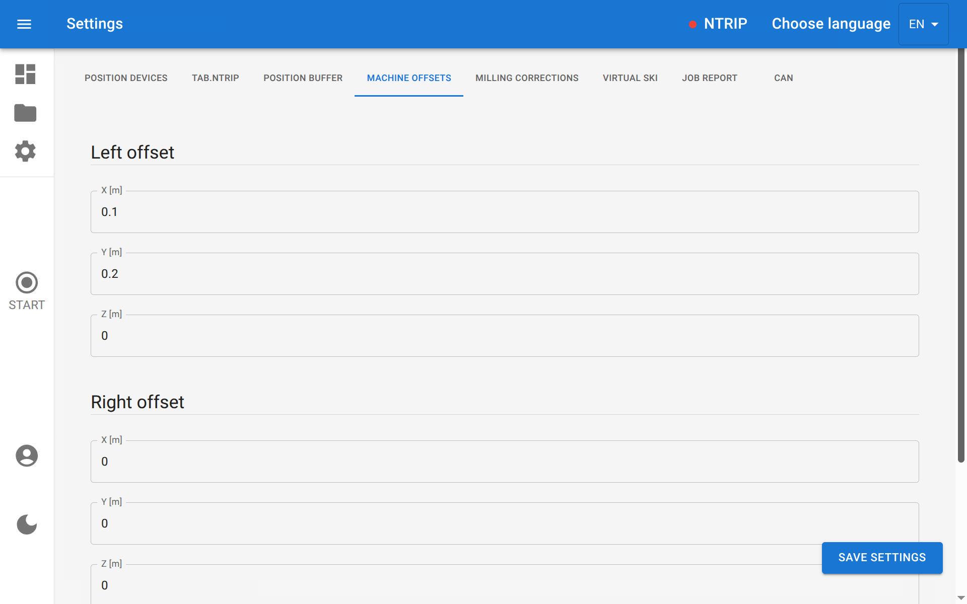
- Enter the values into an Excel spreadsheet (Download) to calculate the calibration values Lx, Ly, Lz, Rx, Ry a Rz.
- Save the calibration values in the DMU program settings.
For point measurement, use either a miniprism (for magnetic holders measurement) or laser prismless measurement (center of side plate etc. measurement)!
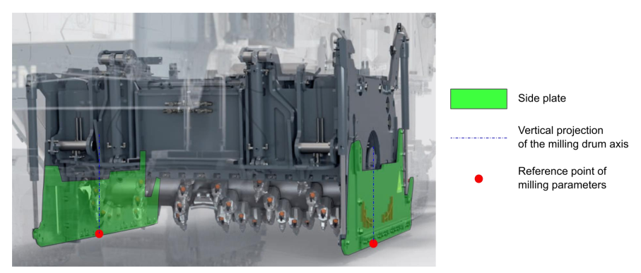
Reference points of milling parameters
Reference points are positions in which are set the milling depths and inclination, these points are in the middle of the thickness of the side plates in the projection of the axis of the milling drum.